
Round-trip Matrix
The function calculates the round-trip matrix of the schema and displays it in a special window. An element selected in the elements list is treated as reference. Multiplication of the elements’ matrices starts from the reference element.
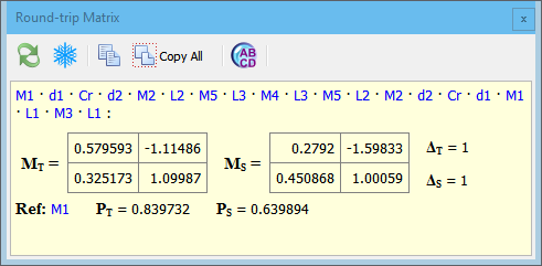
If schema is a resonator (not single-pass system) then the stability parameter of the schema is also calculated.
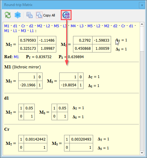
In the upper line the list of elements is shown in that sequence as their matrices are multiplied. You can click each element’s label to open a separate information window displaying element’s matrices.
Optionally all element’s matrices can be displayed right in the window, use the toolbar button:
By default the whole element matrix is used for round-trip calculation. The reference plane placed right after the selected element and matrix multiplication starts from that element. But if an element having the length parameter has been chosen as the reference (e.g. a crystal), then an optional offset inside the element can be set. Then the element gets split into two sub-elements according to the diagram and round-trip matrix inside the element is calculated.
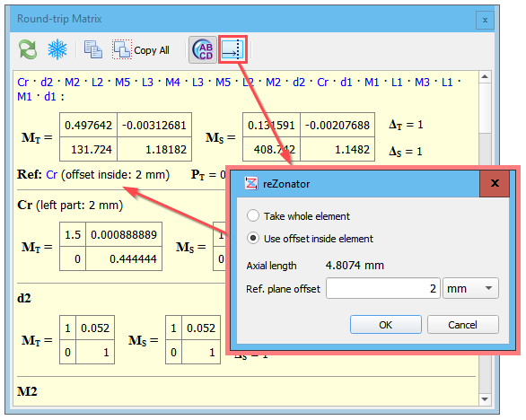
Meaning the general round-trip rule, the beam follows from left to right, then matrices are multiplied from right to left, so this offset is measured from the left edge of the element.
The “Axial length” value in the dialog shows the maximal possible offset and it is the longest geometrical path a beam can travel in the element. For some elements (e.g. Brewster Plane-parallel Plate) the axial length is greater than the element length because there is an angle between optical axis and the direction the length is measured along.